

PCC (Per Connection Classifier) is a powerful load-balancing method in MikroTik that allows you to distribute traffic across multiple WAN connections based on specific attributes. It ensures consistent routing of packets belonging to the same connection through the same WAN, avoiding issues like broken sessions or authentication failures on websites.
How PCC Works
PCC classifies connections based on specific parameters such as:
- Source address (
src-address) - Destination address (
dst-address) - Both source and destination addresses (
both-addresses) - Source port (
src-port) - Destination port (
dst-port)
Each connection is assigned a “hash” value based on the chosen classifier, ensuring that all packets from the same connection follow the same path.
Why Use PCC for Load Balancing?
- Distributes traffic efficiently across multiple WAN links
- Maintains session persistence, preventing connection drops
- Works with dynamic and static IPs
- Can be weighted for different speed connections
PCC for Load Balancing Two WAN Links (Different Speeds)
When your WAN connections have different speeds, a simple 50/50 PCC split is inefficient. Instead, you need to apply weighted load balancing based on available bandwidth.
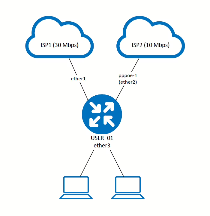
Example Scenario
- WAN1 = 30Mbps
- WAN2 = 10Mbps
- Instead of a 1:1 load balancing ratio, we need to apply a 2:1 ratio (WAN1 should handle twice the traffic of WAN2).
Configuration Steps in MikroTik RouterOS
1. Mark New Connections with PCC
We use Mangle rules in the firewall to classify connections.
Since WAN1 should take twice as much traffic as WAN2, we define three PCC rules:
both-addresses:3/X→ “3” means dividing connections into three groups (2 for WAN1, 1 for WAN2)./0and/1go to WAN1./2goes to WAN2.
2. Mark Routing Based on Connection Mark
Now, we mark packets based on the connection marks created above.
3. Configure Routes to Send Traffic to the Correct Gateways
This ensures that marked traffic is forwarded through the correct WAN gateway.
Configuration
Topology
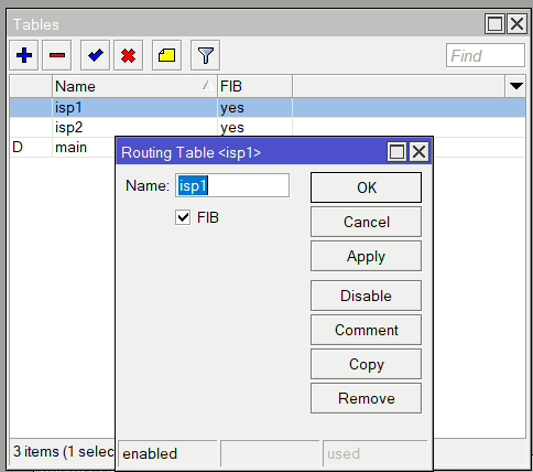
Routing Tables
Start by adding a new Routing Table per ISP connection and check FIB
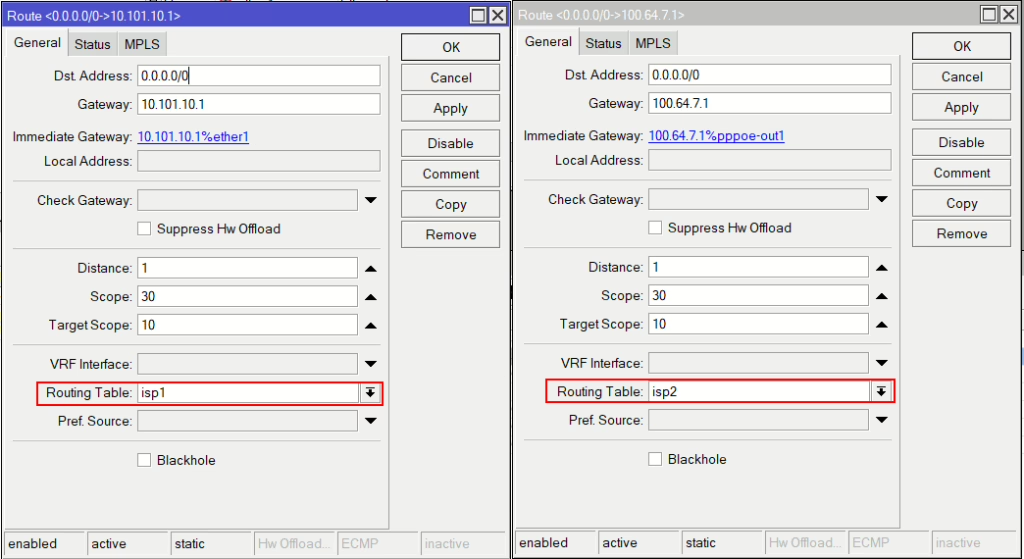
Routes
Add a static route for each gateway and specify the relevant routing table created just before
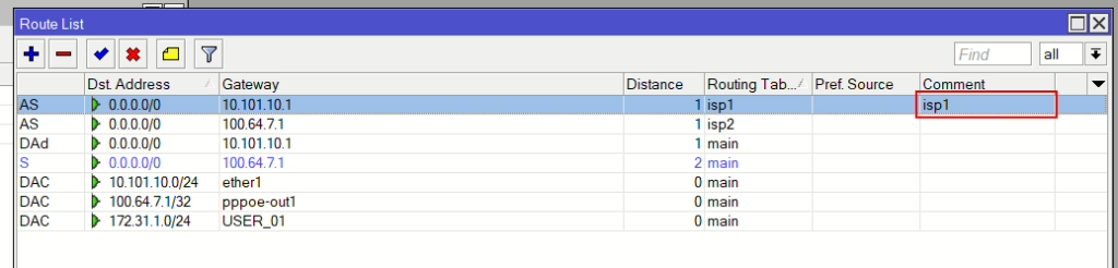
Dynamic IP addresses (optional)
If your WAN IP is provided via DHCP, add the following script to the DHCP Client setting and change the comment=” to match your link, and then make sure that route has the same comment. On receiving an IP the gateway IP will be updated, in case your ISP provides a different gateway IP.
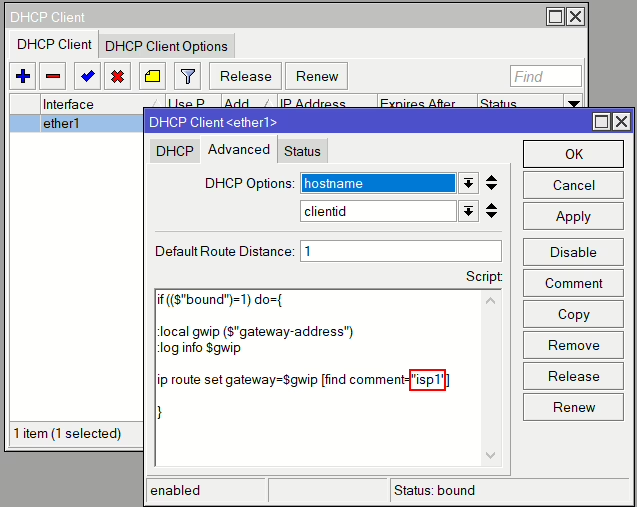
if (($"bound")=1) do={
:local gwip ($"gateway-address")
:log info $gwip
ip route set gateway=$gwip [find comment="isp1"]
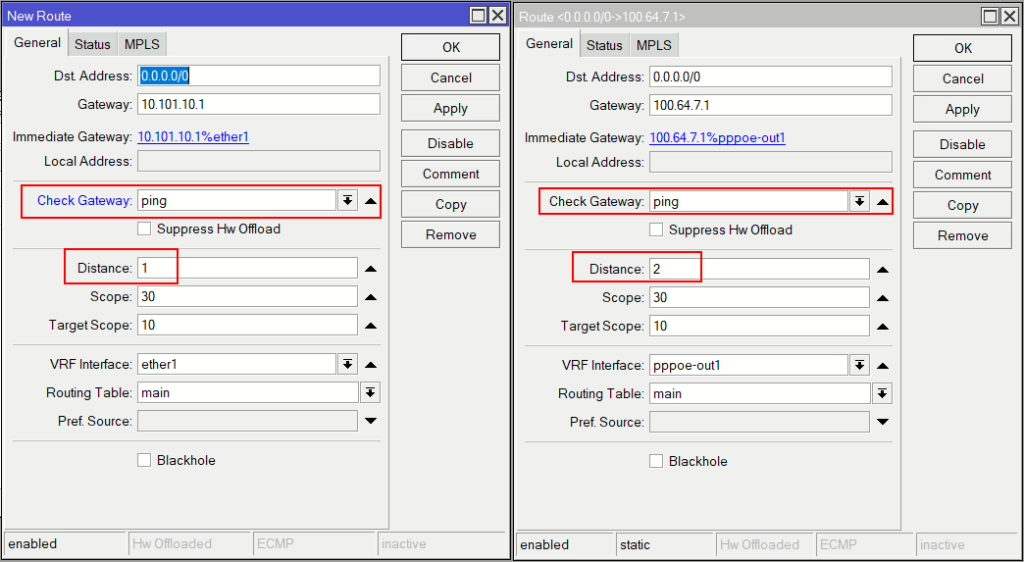
}Gateway Failover
Now for a basic failover, we shall use the Check Gateway feature. Create an additional route per ISP and set the Check Gateway to ping and the primary to a distance of 1 and the second to 2. (Note: If using the dynamic option above make sure the same route has the same comment, e.g. “isp1”)
More mature failover options can be found here: https://mikrotikmasters.com/category/tutorials/internet-failover/
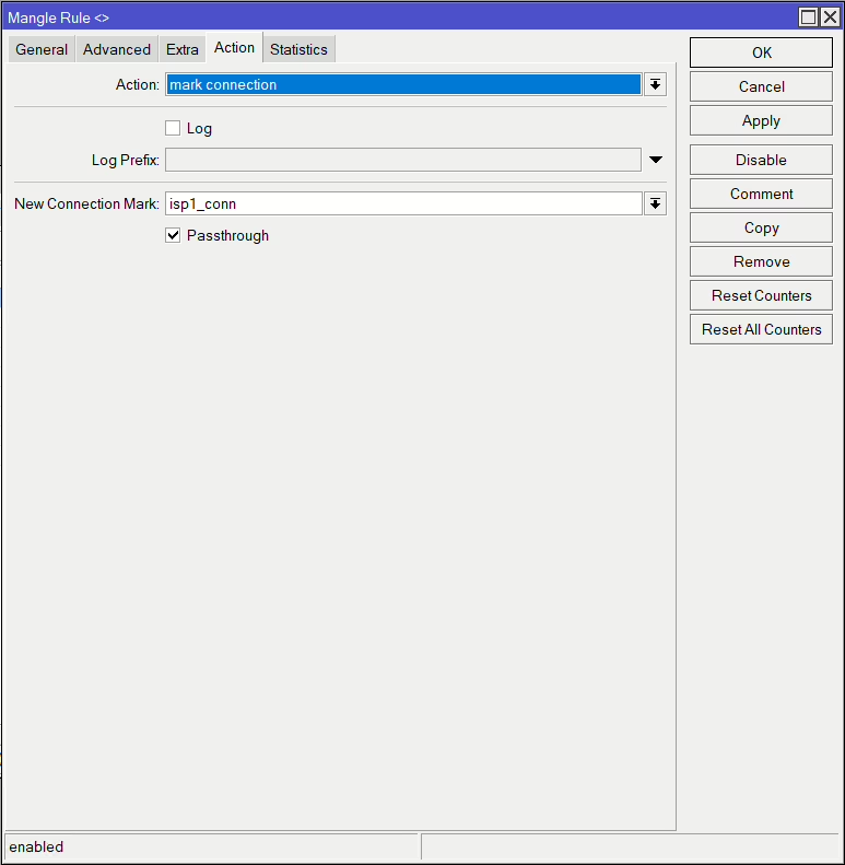
Mangle Rules
First set of rules will be matching incoming traffic from each WAN interface that doens’t have a connection make and classified as a new connection. Then we mark that connection with a unique name for that interface, i.e. for ISP1 (ether1) mark it isp1_conn.
Repeat for ISP2.
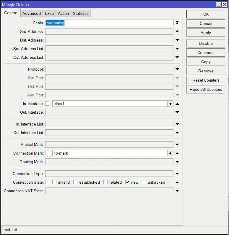
/ip firewall mangle
add action=mark-connection chain=prerouting connection-mark=no-mark connection-state=new in-interface=ether1 new-connection-mark=isp1_conn passthrough=yes
add action=mark-connection chain=prerouting connection-mark=no-mark connection-state=new in-interface=pppoe-out1 new-connection-mark=isp2_conn passthrough=yes
Now that we’ve marked those connections, we use those to match traffic outbound of the router (output chain) and mark the routing, i.e. specifying which routing table to use and in turn which gateway to use.
Anything with connection mark isp2_conn will route via routing table isp2
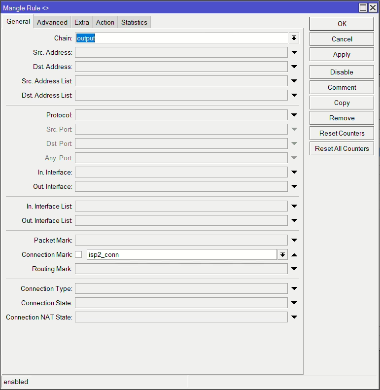
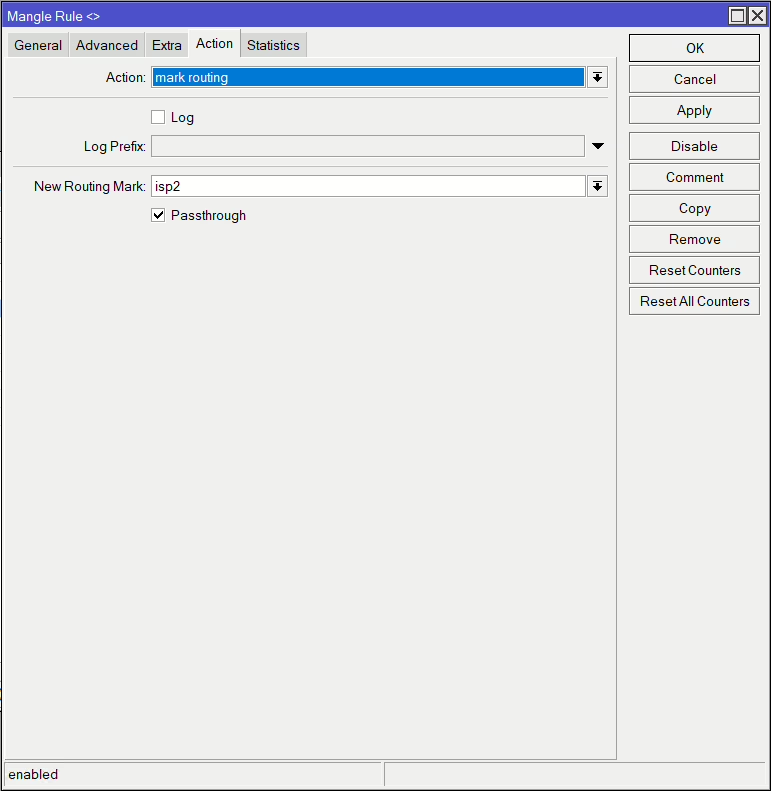
/ip firewall mangle
add action=mark-routing chain=output connection-mark=isp2_conn new-routing-mark=isp2 passthrough=yes
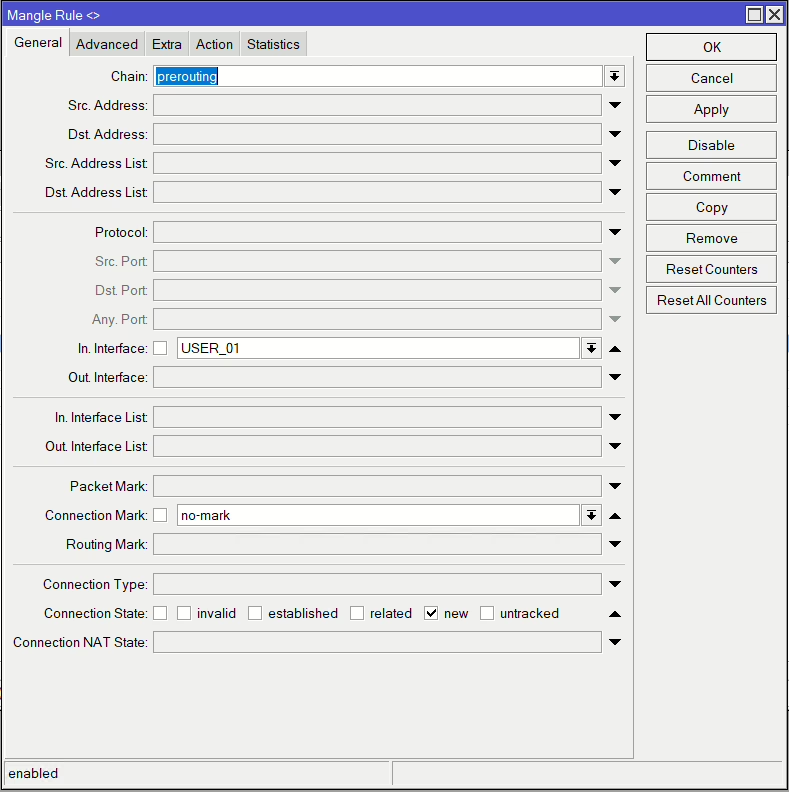
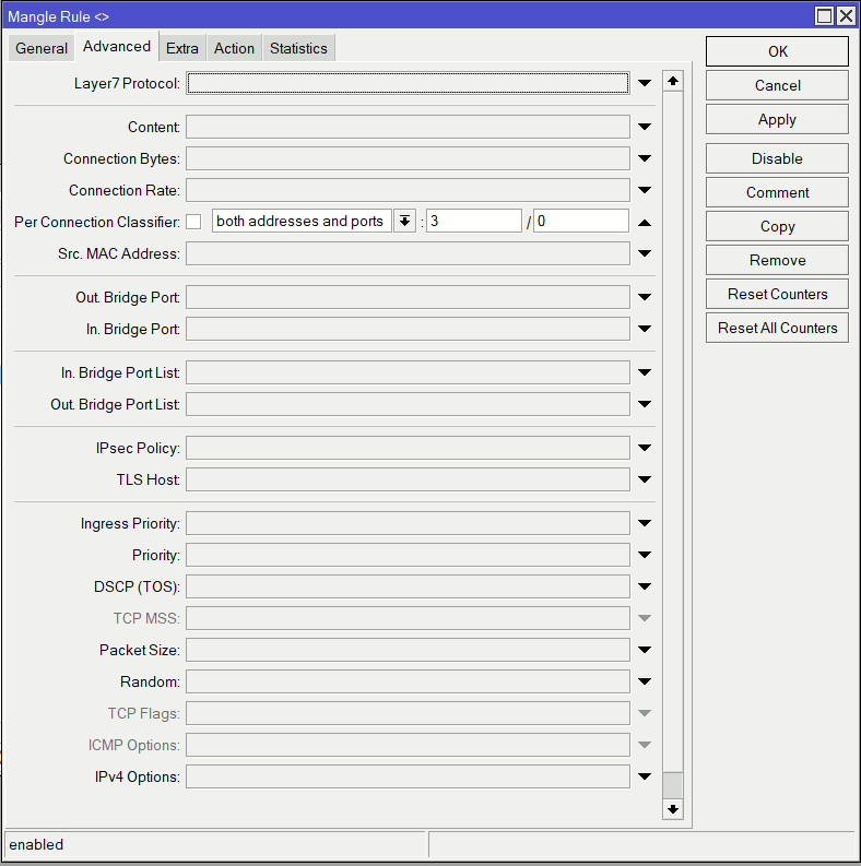
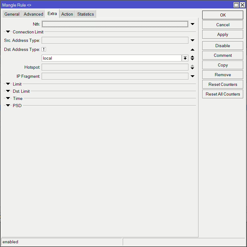
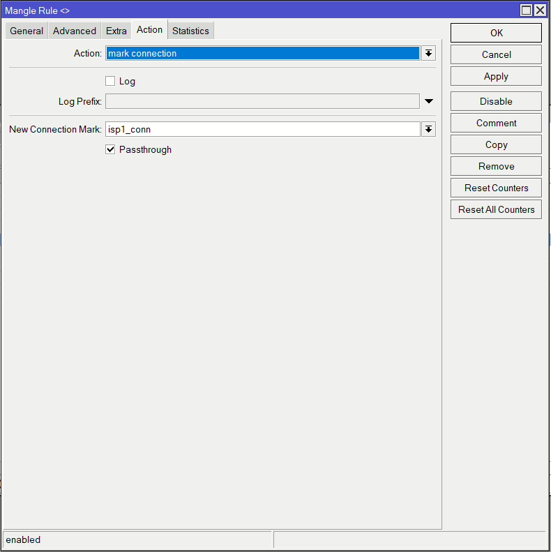
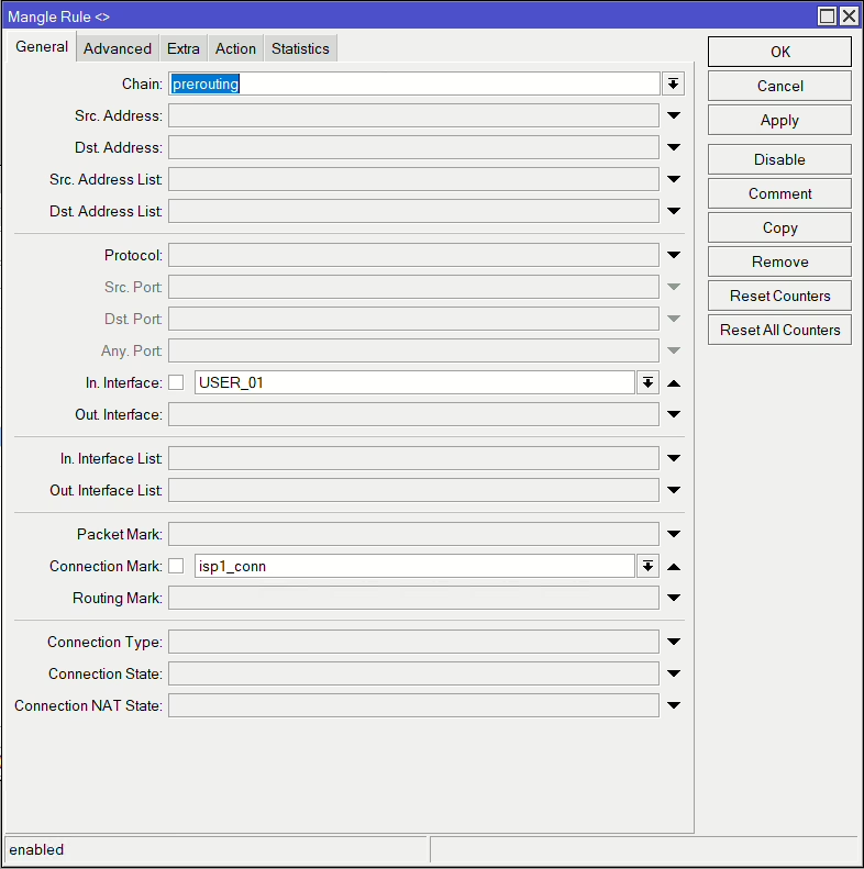
add action=mark-routing chain=output connection-mark=isp1_conn new-routing-mark=isp1 passthrough=yesNow these next rules match and divide up our connections. The below example is the first of two for ISP1. It matches the LAN traffic via our bridge (USER_01), which are new connections without and existing marks. It then also matches it if it’s not designed for any local traffic. The Per Connection Classifier is the ratio we’ve previously decided on, which means we have 3 streams (2 for ISP1 & 1 for ISP2), and the second is which stream number it is (0 = first, 1 = second, etc). We are using both address and ports so each connection that is from the same src and dst and port combination will use the same stream, meaning it’s more likely to randomly spread our traffic over the links.
Then it will mark each connection with he relevant connection mark
| Connection stream | PCC | Connection Mark |
| 1 | 3/0 | isp1_conn |
| 2 | 3/1 | isp1_conn |
| 3 | 3/2 | isp2_conn |
/ip firewall mangle
add action=mark-connection chain=prerouting connection-mark=no-mark connection-state=new dst-address-type=!local in-interface=USER_01 new-connection-mark=isp1_conn passthrough=yes per-connection-classifier=both-addresses-and-ports:3/0
add action=mark-connection chain=prerouting connection-mark=no-mark connection-state=new dst-address-type=!local in-interface=USER_01 new-connection-mark=isp2_conn passthrough=yes per-connection-classifier=both-addresses-and-ports:3/2
add action=mark-connection chain=prerouting connection-mark=no-mark connection-state=new dst-address-type=!local in-interface=USER_01 new-connection-mark=isp1_conn passthrough=yes per-connection-classifier=both-addresses-and-ports:3/1
The last rules then use those connection marks like before and apply the relevant routing mark to determine which routing table the traffic uses

/ip firewall mangle
add action=mark-routing chain=prerouting connection-mark=isp1_conn in-interface=USER_01 new-routing-mark=isp1 passthrough=yes
add action=mark-routing chain=prerouting connection-mark=isp2_conn in-interface=USER_01 new-routing-mark=isp2 passthrough=yes
Now we have a full set of rules
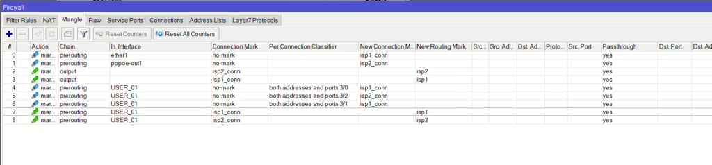
Full list
/ip firewall mangle
add action=mark-connection chain=prerouting connection-mark=no-mark connection-state=new in-interface=ether1 new-connection-mark=isp1_conn passthrough=yes
add action=mark-connection chain=prerouting connection-mark=no-mark connection-state=new in-interface=pppoe-out1 new-connection-mark=isp2_conn passthrough=yes
add action=mark-routing chain=output connection-mark=isp2_conn new-routing-mark=isp2 passthrough=yes
add action=mark-routing chain=output connection-mark=isp1_conn new-routing-mark=isp1 passthrough=yes
add action=mark-connection chain=prerouting connection-mark=no-mark connection-state=new dst-address-type=!local in-interface=USER_01 new-connection-mark=isp1_conn passthrough=yes \
    per-connection-classifier=both-addresses-and-ports:3/0
add action=mark-connection chain=prerouting connection-mark=no-mark connection-state=new dst-address-type=!local in-interface=USER_01 new-connection-mark=isp2_conn passthrough=yes \
    per-connection-classifier=both-addresses-and-ports:3/2
add action=mark-connection chain=prerouting connection-mark=no-mark connection-state=new dst-address-type=!local in-interface=USER_01 new-connection-mark=isp1_conn passthrough=yes \
    per-connection-classifier=both-addresses-and-ports:3/1
add action=mark-routing chain=prerouting connection-mark=isp1_conn in-interface=USER_01 new-routing-mark=isp1 passthrough=yes
add action=mark-routing chain=prerouting connection-mark=isp2_conn in-interface=USER_01 new-routing-mark=isp2 passthrough=yes

